
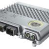

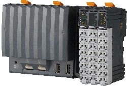
Bộ lập trình X90CP154.60-S1
Thông số kỹ thuật bộ lập trình B&R X90CP154.60-S1
đại lý X90CP154.60-S1 | nhà phân phối X90CP154.60-S1 | đại lý B&R | B&R Việt Nam
Mô tả ngắn gọn
| Giao diện | 1x Ethernet/POWERLINK (switchable), 1x POWERLINK, 3x CAN bus, 1x LIN bus, 1x RS232, 1x USB |
| Mô-đun hệ thống | Bộ điều khiển B&R |
Thông tin chung
| Insulation voltage for GND and housing | 500 Veff |
| B&R ID code | 0x29AC |
| System requirements | |
| Automation Studio | 4.12 or later |
| Automation Runtime | K4.93 and later |
| mapp Technology Package | mapp Safety 5.22 or later |
| Làm mát | Fanless |
| Chỉ số trạng thái | Bộ điều khiển B&R function, operating state, overtemperature, Ethernet, POWERLINK, safety function |
| Chẩn đoán | |
| Module run/error | Yes, using LED status indicator, software and diagnostic output |
| CPU function | Yes, using LED status indicator |
| Ethernet | Yes, using LED status indicator |
| Safety function | Yes, using LED status indicator |
| Hỗ trợ | |
| Bộ điều khiển B&R redundancy | No |
| Hỗ trợ dữ liệu sức khỏe lưu trữ | Yes |
| ACOPOS support | Yes |
| reACTION-capable I/O channels | No |
| Hỗ trợ thành phần trực quan | Yes |
| Tiêu thụ điện năng | CPU at Ue = 9 / 32 V: 5.5 / 6.7 W |
| Max. I/O cycle time | 2 ms |
| Chứng nhận | |
| UN ECE-R10 | In preparation |
| CE | Yes |
| UKCA | Yes |
| Functional safety | In preparation |
| Functional safety |
IEC 61508 in preparation EN 62061 in preparation EN ISO 13849-1 in preparation EN ISO 13766-2 in preparation EN ISO 25119 in preparation |
Safety characteristics
| Note | See section “Safety characteristics” in data sheet. |
Functionality
| Hỗ trợ for Safe Commissioning Options | |
| BOOL | 64 |
| INT | 16 |
| UINT | 16 |
| DINT | 12 |
| UDINT | 12 |
| SafeMOTION support | Yes |
| Max. number of SafeMOTION axes | 6, depends on the data width of the modules used |
| Timing precision | Time * 0.05 + Cycle time of the safety application |
| Max. number of SafeNODEs | 10, depends on the data width of the modules used |
| Data exchange between CPU and SafeLOGIC controller | |
| Max. total data width for each direction | 48 bytes |
| Max. number of data points for each direction | |
| BOOL | 128 |
| INT | 16 |
| UINT | 16 |
| DINT | 8 |
| UDINT | 8 |
| Data exchange between SafeDOMAIN and SafeDOMAIN | |
| Use as Managing SafeDOMAIN | Yes |
| Use as Connected SafeDOMAIN | Yes |
| Max. total data width for each direction | 8 bytes |
| Max. total number of data points for each direction | 4 |
| Max. number of data points for each direction | |
| BOOL | 16 |
| INT | 2 |
| UINT | 2 |
| DINT | 2 |
| UDINT | 2 |
| Max. number of linked Managing SafeDOMAINs | 1 |
Limit values for SafeDESIGNER application
| Max. resources available for SafeDESIGNER info window entries | |
| FB instances | 256 |
| Marker memory | 5120 bytes (0x1400) |
| Stack memory | 8192 bytes |
| Memory for safe input data | 512 bytes, 68 bytes of which are usable for modules |
| Memory for safe output data | 128 bytes |
| Memory for standard input data | 128 bytes |
| Memory for standard output data | 128 bytes |
| Marker count | 512 |
| Additional SafeDESIGNER limit values | |
| Max. number of function block types | 64 |
| Max. number of force variables | 16 |
| Max. number of variable with variable status | 128 |
Input power supply
| Input voltage | 9 to 32 VDC |
| Input voltage V_CPU, V_I/O | |
| Nominal voltage 12 V | 9 to 16 VDC |
| Nominal voltage 24 V | 16 to 32 VDC |
| Reset switching threshold | 5.4 V |
| Input current | |
| V_CPU | During operation Typ. 420 mA at 12 V Typ. 240 mA at 24 V In standby mode Typ. 18 mA at 12 V Typ. 13 mA at 24 V |
| V_I/O | Max. 10 A per connection pin |
| Integrated protection | |
| V_CPU | No, required fuse 5 A slow-blow |
| V_I/O | No, required fuse 10 A slow-blow per connection pin |
| Overvoltage | Max. 48 V |
| Overvoltage protection | Load dump pulse A 202 V Ri = 4 Ω |
| Reverse polarity protection | Max. -48 V |
Bộ điều khiển B&R
| Đồng hồ thời gian thực | Resolution 1 s, retention min. 200 hours, typ. 1000 hours at 25°C, precision ±8 ppm over the entire temperature range |
| FPU | Yes |
| Bộ xử lý | |
| Kiểu | ARM Cortex-A9 |
| Tần số đồng hồ | 650 MHz |
| L1 cache | |
| Mã dữ liệu | 32 kB |
| Mã chương trình | 32 kB |
| L2 cache | 512 kB |
| Bộ xử lý I/O tích hợp | Processes I/O data points in the background |
| Option boards | Not available |
| Các biến số | 32 kB FRAM, retention >10 years |
| Thời gian chu kỳ lớp nhiệm vụ ngắn nhất | 400 µs |
| Bộ nhớ chuẩn | |
| RAM | 512 MB DDR3 SDRAM |
| Bộ nhớ ứng dụng | |
| Kiểu | 4 GB flash memory |
| Lưu giữ dữ liệu | 10 years |
| Lượng dữ liệu có thể ghi | |
| Đảm bảo | 100 TB |
| Kết quả trong 5 năm | 54.8 GB/day |
| Đảm bảo erase/write cycles | 100,000 |
| Mã sửa lỗi (ECC) | Yes |
Giao diện
| Interface IF1 | |
| Kiểu | RS232 |
| Khác nhau | Connection on CMC header X1.A |
| Max. distance | 3 m |
| Tỷ lệ chuyển nhượng | Max. 115.2 kbit/s |
| Interface IF2 | |
| Kiểu | Ethernet / POWERLINK |
| Khác nhau | M12, D-coded |
| Chiều dài dòng | Max. 100 m between 2 stations (segment length) |
| Tỷ lệ chuyển nhượng | 10/100 Mbit/s |
| Transfer | |
| Lớp vật lý | 10BASE-T/100BASE-TX |
| Half-duplex | Yes |
| Full-duplex | Yes |
| Autonegotiation | Yes |
| Auto-MDI/MDIX | Yes |
| Interface IF3 | |
| Fieldbus | POWERLINK managing or controlled node |
| Kiểu | Kiểu 6 |
| Khác nhau | M12, D-coded |
| Chiều dài dòng | Max. 100 m between 2 stations (segment length) |
| Tỷ lệ chuyển nhượng | 100 Mbit/s |
| Transfer | |
| Lớp vật lý | 100BASE-TX |
| Half-duplex | Yes |
| Full-duplex | No |
| Autonegotiation | Yes |
| Auto-MDI/MDIX | Yes |
| Interface IF4 | |
| Kiểu | USB 1.1/2.0 |
| Khác nhau | Kiểu A (under service access window) |
| Max. output current | 500 mA |
| Interface IF5 | |
| Kiểu | LIN |
| Khác nhau | Connection on CMC header X1.A |
| Max. distance | 40 m |
| Tỷ lệ chuyển nhượng | Max. 20 kbit/s |
| Interface IF7 | |
| Connection designation | CAN1 |
| Kiểu | CAN bus |
| Khác nhau | Connection on CMC header X1.A |
| Max. distance | 1000 m |
| Tỷ lệ chuyển nhượng | Max. 1 Mbit/s |
| Terminating resistor | External 120 Ω must be provided. |
| Interface IF8 | |
| Connection designation | CAN2 |
| Kiểu | CAN bus |
| Khác nhau | Connection on CMC header X1.A |
| Max. distance | 1000 m |
| Tỷ lệ chuyển nhượng | Max. 1 Mbit/s |
| Terminating resistor | External 120 Ω must be provided. |
| Interface IF9 | |
| Connection designation | CAN3 |
| Kiểu | CAN bus |
| Khác nhau | Connection on CMC header X1.A |
| Max. distance | 1000 m |
| Tỷ lệ chuyển nhượng | Max. 1 Mbit/s |
| Terminating resistor | External 120 Ω must be provided. |
Multi-function inputs
| Multifunction digital inputs MF-DI (std) | |
| Quantity | 2 |
| Function | Safe digital input Kiểu B, sink circuit, configurable software input filter Digital input Sink/Source circuit – Configurable per channel, configurable software input filter |
| Multifunction digital inputs MF-DI (CI) | |
| Quantity | 8 |
| Function | Safe digital input Kiểu B, sink circuit, configurable software input filter Safe counter input (channels 1 to 4 only) Kiểu B, sink circuit, configurable software input filter, 2x counter function up to 50 kHz counter frequency (2xAB, 2xAA or 4xA) Digital input Sink/Source circuit – Configurable per channel, configurable software input filter, counter function up to 50 kHz counter frequency (max. 4x AB, max. 2x ABR, max. 2x DF, max. 8x edge counter), edge detection with timestamp (for period duration, gate time measurement, differential time measurement) |
| Multifunction analog inputs MF-AI (std) | |
| Quantity | 4 |
| Function | Digital input Sink/Source circuit – Configurable per channel, configurable software input filter, fixed or ratiometrically configurable switching threshold. Analog input Measurement range 0 to 10 V / 0 to 32 V / 0/4 to 20 mA, configurable analog filter, configurable ramp limit, configurable threshold values, integrated input protection |
| Multifunction analog inputs MF-AI (AT) | |
| Quantity | 8 |
| Function | Kiểu B, sink circuit, configurable software input filter Kiểu B, measurement range 0 to 10 V / 0 to 32 V / 0 to 20 mA / 0 to 4000 Ω Digital input (without diagnostics) Sink/Source circuit – Configurable per channel, configurable software input filter, fixed or ratiometrically configurable switching threshold. Digital input (with diagnostics) Configurable software input filter, open-circuit and short-circuit detection. Analog input Measurement range 0 to 10 V / 0 to 32 V / 0/4 to 20 mA / 0 to 4000 Ω / temperature inputs (Pt1000 characteristic curve), configurable analog filter, configurable ramp limit, configurable threshold values, integrated input protection |
| Multifunction analog inputs MF-AI (PVG) | |
| Quantity | 8 |
| Function | Kiểu B, sink circuit, configurable software input filter Kiểu B, measurement range 0 to 10 V / 0 to 32 V / 0 to 20 mA / 0 to 4000 Ω Digital input (without diagnostics) Sink/Source circuit – Configurable per channel, configurable software input filter, fixed or ratiometrically configurable switching threshold. Digital input (with diagnostics) Configurable software input filter, open-circuit and short-circuit detection. Analog input Measurement range 0 to 10 V / 0 to 32 V / 0/4 to 20 mA / 0 to 4000 Ω / temperature inputs (Pt1000 characteristic curve), configurable analog filter, configurable ramp limit, configurable threshold values, integrated input protection Ratiometric analog output (smoothed PWM signal) Short-circuit current 5.5 mA max. at 24 V, PWM frequency 25 kHz PVG Short-circuit current 5.5 mA max. at 24 V, PVG frequency 25 kHz. |
Multi-function outputs
| Multifunction digital outputs (MF-DO) | |
| Quantity | 8 |
| Functions | Kiểu C, 4 A nominal current, source circuit, integrated output protection per channel, central cutoff via relay, error state 4 A nominal current, source circuit, integrated output protection per channel, configurable overload monitoring per channel, central cutoff via relay,parallel connection, current measurement, error state with configurable error filter Digital inputs, sink/source circuit configurable per channel, configurable software input filter |
| Multifunction PWM outputs MF-PWM (std) | |
| Quantity | 16 |
| Function | Kiểu C, 4 A nominal current (PWM 4 A), 6 A nominal current (PWM 6 A), source circuit, integrated output protection per channel, central cutoff via relay, error state Digital output 4 A nominal current, source circuit, integrated output protection per channel, configurable overload monitoring per channel, central cutoff via relay,parallel connection, current measurement, error state with configurable error filter. PWM output 4 A nominal current, PWM frequency 15 Hz to 1 kHz, source circuit, integrated output protection per channel, configurable overload monitoring per channel, central cutoff via relay, parallel connection, current measurement, configurable switching edge shift to avoid load peaks, dither. Digital input Sink/Source circuit configurable per channel, configurable software input filter |
| Multifunction PWM outputs MF-PWM (bridge) | |
| Quantity | 6 |
| Function | Kiểu C, 4 A nominal current (PWM 4 A), 6 A nominal current (PWM 6 A), source circuit, integrated output protection per channel, central cutoff via relay, error state Digital output 6 A nominal current, push-pull circuit, integrated output protection per channel, configurable overload monitoring per channel, central cutoff via relay,parallel connection, current measurement, error state with configurable error filter. PWM output 6 A nominal current, PWM frequency 15 Hz to 4 kHz, 8 kHz in full-bridge mode, push-pull circuit, integrated output protection per channel, configurable overload monitoring per channel, central cutoff via relay, parallel connection, current measurement, configurable load current distribution of the PWM outputs, dither. Digital input Sink/Source circuit configurable per channel, configurable software input filter |
Digital inputs
| Quantity | 8 to 60, depends on the use of multifunction inputs/outputs |
| Nominal voltage | 12 / 24 VDC |
| Input voltage | 9 to 32 VDC |
| Input current at 24 VDC |
MF-DI (CI + std): Typ. 1.1 / 2.5 mA, configurable MF-AI (AT + PVG): Typ. 1.1 / 5.3 mA, configurable MF-AI (std): Typ. 1.1 mA MF-DO (std): Typ. 2.5 mA MF-PWM (all): Typ. 2.5 mA |
| Input circuit | Sink/Source, configurable |
| Input filter | |
| Hardware |
MF-DI: 3 µs MF-AI (all): 300 µs MF-DO: 150 µs MF-PWM (bridge): 200 µs MF-PWM (std): 150 µs |
| Software | Default 1 ms, configurable between 0 and 25 ms in 0.1 ms increments |
| Input resistance |
MF-DI (CI + std): Typ. 9.15 / 20.2 kΩ, configurable MF-AI (AT + PVG): Typ. 4.42 / 22.1 kΩ, configurable MF-AI (std): Typ. 22 kΩ MF-DO (std): Typ. 9.15 kΩ MF-PWM (all): Typ. 9.15 kΩ |
| Input frequency | MF-DI: Max. 50 kHz |
| Switching threshold |
MF-DI: 50% of supply voltage MF-AI (all): Switching threshold and hysteresis configurable with software MF-DO: 40% supply voltage MF-PWM (all): 40% supply voltage |
Safe digital inputs
| Quantity | 10 to 26, depends on the use of multifunction inputs |
| Khác nhau | Kiểu B |
| Nominal voltage | 12 / 24 VDC |
| Input filter | |
| Hardware |
MF-DI: 4 μs if switching threshold = 50% supply voltage MF-AI: 300 μs if switching threshold = 50% supply voltage |
| Software | Default T_on = 256 ms / T_off = 0 ms, configurable between 0 and 1024 ms |
| Input circuit | Sink |
| Input voltage | 9 to 32 VDC |
| Input current at 24 VDC |
MF-DI: Typ. 1.4 / 3.8 mA, configurable MF-AI: Typ. 1.4 / 5.7 mA, configurable |
| Input resistance |
MF-DI: Typ. 8.6 / 17.8 kΩ, configurable MF-AI: Typ. 4.2 / 18.3 kΩ, configurable |
| Error detection time | Max. 8 hours |
| Switching threshold | |
| Low |
MF-DI: <40% of supply voltage MF-AI: 50% of supply voltage |
| High |
MF-DI: >60% of supply voltage MF-AI: 50% of supply voltage |
Safe digital counter inputs
| Quantity | 2x (1xAB, 1xAA or 2xA) |
| Khác nhau | Kiểu B |
| Nominal voltage | 12 / 24 VDC |
| Input filter | |
| Hardware | 4 μs at switching threshold = 50% supply voltage |
| Software | 10 to 100 ms, configurable |
| Input frequency | MF-DI: Max. 50 kHz |
| Input circuit | Sink |
| Input voltage | 9 to 32 VDC |
| Input current at 24 VDC | Typ. 1.4 / 3.8 mA, configurable |
| Input resistance | Typ. 8.6 / 17.8 kΩ, configurable |
| Switching threshold | |
| Low | <40% of supply voltage |
| High | >60% of supply voltage |
Analog inputs
| Quantity | 0 to 20, depends on the use of multifunction inputs |
| Input | 0 to 10 V / 0 to 32 V / 0/4 to 20 mA / 0 to 4000 Ω / Nhiệt độ inputs (Pt1000 characteristic curve) |
| Digital converter resolution | 12-bit |
| Conversion time | 160 μs |
| Output format | |
| Data type | INT |
| Voltage |
0 to 10 V: INT 0x0000 – 0x7FFF / 1 LSB = 0x0008 = 2.441 mV 0 to 32 V: INT 0x0000 – 0x7FFF / 1 LSB = 0x0008 = 7.812 mV |
| Current | 0x0000 – 0x7FFF / 1 LSB = 0x0008 = 4.883 µA |
| Resistance | 0 to 4000, resolution 1 Ω |
| Nhiệt độ input | -200 to 850, resolution 0.1°C |
| Input impedance in signal range | |
| Voltage | >100 kΩ |
| Current | – |
| Measurement current resistance / Nhiệt độ input | <2.2 mA |
| Load | |
| Voltage | – |
| Current | 100 Ω |
| Open-circuit detection | From the application |
| Conversion procedure | SAR |
| Input filter | First-order low-pass filter / cutoff frequency of voltage input 350 Hz, current input 200 Hz |
| Max. error | |
| Voltage | |
| Gain | <1.5% |
| Offset | <1.5% |
| Current | |
| Gain | <1.5% |
| Offset | <1.5% |
| Resistance | <5% |
| Nhiệt độ input | <5% |
| Max. gain drift | |
| Voltage | <0.03%/°C |
| Current | <0.04%/°C |
| Resistance | <0.034%/°C |
| Nhiệt độ input | <0.024%/°C |
| Max. offset drift | |
| Voltage | <0.06%/°C |
| Current | <0.06%/°C |
| Resistance | <0.018%/°C |
| Nhiệt độ input | <0.027%/°C |
| Nonlinearity |
<0.05% (resistance) <0.2% (temperature inputs) |
Safe analog inputs
| Khác nhau | Kiểu B |
| Input type | 0 to 10 V / 0 to 32 V / 0 to 20 mA / 0 to 4 kΩ |
| Digital converter resolution | 12-bit |
| Conversion time | 20 ms |
| Output format | |
| Data type | INT |
| Voltage |
Voltage 0 to 10 V: INT 0x0000 – 0x7FFF / 1 LSB = 0.305 mV Voltage 0 to 32 V: INT 0x0000 – 0x7FFF / 1 LSB = 0.97625 mV |
| Current | INT 0x0000 – 0x7FFF / 1 LSB = 0.610 µA |
| Resistance | Resistance 0 to 4 kΩ: INT 0x0000 – 0xFA0 / 1 LSB = 1 Ω |
| Input impedance in signal range | |
| Voltage | 100 kΩ |
| Current | – |
| Load | |
| Voltage | – |
| Current | <300 Ω |
| Open-circuit detection | From the application |
| Reverse polarity protection | Yes |
| Conversion procedure | SAR |
| Input filter |
First-order low-pass filter / cutoff frequencies: 0 to 32 V: 400 Hz, 0 to 10 V: 350 Hz, 0 to 20 mA: 200 Hz |
| Max. error at 25°C | |
| Voltage | |
| Gain | <1.5% |
| Offset | <1.5% |
| Current | |
| Gain | <1.5% |
| Offset | <1.5% |
| Max. gain drift | |
| Voltage | <0.03%/°C |
| Current | <0.06%/°C |
| Resistance | <0.02%/°C |
| Max. offset drift | |
| Voltage | <0.02%/°C |
| Current | <0.03%/°C |
| Resistance | <0.04%/°C |
| Nonlinearity | <0.2% |
| Noise | <0.7% |
| Error with sensor internal resistance >1 kΩ |
0 to 20 mA: – 0 to 10 V / 0 to 32 V: 1.1% |
| Internal sensor resistance for single-channel use | Max. 200 Ω |
| Safety-related accuracy per channel | |
| Single-channel |
0 to 32 V: 18 0 to 10 V: 12 0 to 20 mA: 20% |
| Dual-channel |
0 to 10 V / 0 to 32 V: 10% 0 to 20 mA: 11% 0 to 4 kΩ: 14% |
Sensor power supply
| Voltage | 5/10 V |
| Current | Max. 400 mA ±3% |
Digital outputs
| Quantity | 0 to 30, depends on the use of multifunction outputs |
| Khác nhau |
MF-DO: Current-sourcing sinking FET, channels can be connected in parallel in pairs. MF-PWM (bridge): Current-sourcing/Current-sinking FET, channels can be connected in parallel. MF-PWM (std): Current-sourcing sinking FET, channels can be connected in parallel in pairs. |
| Nominal voltage | 12 / 24 VDC |
| Switching voltage |
MF-DO, MF-PWM: V_IO -15% MF-PVG, MF-AI (ratiometric output) : V_CPU – 15% |
| Digital converter resolution | 12-bit |
| Nominal output current |
MF-DO: 4 A MF-PWM (bridge): 6 A MF-PWM (std): 4 A |
| Output protection |
Thermal shutdown in the event of overcurrent or short circuit, MF-PWM only (all): Integrated protection for switching inductances |
| Diagnostic status | Overload |
| Leakage current when the output is switched off |
MF-DO: Typ. 10 μA, max. 4.1 mA MF-PWM (bridge): Typ. 20 μA, max. 4.1 mA MF-PWM (std): Typ. 10 μA, max. 4.1 mA |
| RDS(on) |
MF-DO: <80 mΩ MF-PWM (all): <50 mΩ |
| Residual voltage | <1 V at 4 A nominal current |
| Internal capacity | 2.2 mF |
| Peak short-circuit current |
MF-DO: 90 A MF-PWM (bridge): 50 A MF-PWM (std): 90 A |
| Switching frequency | |
| Resistive load | MF-DO: Max. 250 Hz |
| Inductive load | MF-DO: Load current 4 A: Max. 4 mH (see section “Switching inductive loads”) |
| Braking voltage when switching off inductive loads |
MF-DO: Typ. 64 VDC MF-PWM (std): Typ. 64 VDC |
| Switching delay |
MF-DO: Max. 150 μs MF-PWM (all): Max. 150 μs |
| Output voltage | |
| Nominal | 9 to 32 VDC |
| Sampling time |
MF-DO: 160 μs MF-PWM (bridge): 40 µs MF-PWM (std): 80 μs |
| Current measurement | |
| Current measurement range |
MF-DO: 0 to 20 A MF-PWM (bridge): ±10 A MF-PWM (std): 0 to 10 A |
| Resolution |
INT MF-DO: INT 0x0000 to 0x7FFF / 1 LSB = 610 µA MF-PWM (bridge): INT 0x8001 to 0x7FFF / 1 LSB = 305 μA MF-PWM (std): INT 0x0000 to 0x7FFF / 1 LSB = 305 μA |
| Max. error at 25°C | |
| Gain |
MF-DO: <12% MF-PWM (bridge): <0.5% MF-PWM (std): <3% |
| Offset |
MF-DO: <1% MF-PWM (bridge): <0.25% MF-PWM (std): <1.5% |
| Max. gain drift |
MF-DO: <0.2%/°C MF-PWM (bridge): <0.04%/°C MF-PWM (std): <0.2%/°C |
| Max. offset drift |
MF-DO: <0.005%/°C MF-PWM (all): <0.005%/°C |
Safe digital outputs
| Quantity | 0 to 30, depends on the use of multifunction outputs |
| Khác nhau |
Kiểu C MF-DO: Current-sourcing FET MF-PWM (bridge): Current-sourcing/Current-sinking FET MF-PWM (std): Current-sourcing FET |
| Nominal voltage | 12 / 24 VDC |
| Nominal output current |
MF-DO: 4 A MF-PWM (all): 4 A / 6 A |
| Output protection | Thermal shutdown in the event of overcurrent or short circuit, integrated protection for switching inductive loads |
| Braking voltage when switching off inductive loads | MF-DO: Typ. 64 VDC |
| Diagnostic status | Overload |
| Error detection time | Max. 8 hours |
| Peak short-circuit current |
MF-DO: 90 A MF-PWM (all): 50 A |
| Leakage current when the output is switched off |
MF-DO: Typ. 10 μA, max. 1 mA MF-PWM (all): Typ. 20 μA, max. 1 mA |
| RDS(on) |
MF-DO: 80 mΩ MF-PWM (bridge): <50 mΩ MF-PWM (std): 80 mΩ |
| Residual voltage | <1 V at 4 A nominal current |
| Switching frequency | |
| Resistive load | MF-DO: Max. 250 Hz |
| Inductive load | MF-DO: Load current 4 A: Max. 4 mH (see section “Switching inductive loads”) |
| Switching delay | MF-DO: Max. 150 µs |
| Length of OSSD pulses | <750 µs |
| Max. capacitive load | MF-DO: 4.7 nF |
| Output voltage | |
| Nominal | 9 to 32 VDC |
PWM output
| Quantity |
MF-PWM (bridge): 0 to 6x 6 A MF-PWM (std): 0 to 16x 4 A Depends on the use of multifunction outputs |
| Nominal voltage | 12 / 24 VDC |
| Supply voltage (permissible range) | 9 to 32 VDC |
| Digital converter resolution | 12-bit |
| PWM frequency |
MF-PWM (bridge): 15 Hz to 4 kHz MF-PWM (std): 15 Hz to 1 kHz |
| Duty cycle |
PWM (bridge): 0 to 32767 or -32767, min. resolution 160 ns depending on PWM frequency PWM (std): 0 to 32767, min. resolution 160 ns depending on PWM frequency |
| Max. error at 25°C | |
| Gain |
MF-PWM (bridge): <0.5% MF-PWM (std): <3% |
| Offset |
MF-PWM (bridge): <0.25% MF-PWM (std): <1.5% |
| Max. gain drift |
MF-PWM (bridge): <0.04%/°C MF-PWM (std): <0.2%/°C |
| Max. offset drift | MF-PWM (all): <0.005%/°C |
| Common mode error | MF-PWM (all): 0.01%/V |
| Output protection | Thermal shutdown in the event of overcurrent or short circuit, integrated protection for switching inductive loads |
| Khác nhau |
MF-PWM (bridge): Current-sourcing/Current-sinking FET, channels can be connected in parallel. MF-PWM (std): Channels can be connected in parallel in pairs. |
| Diagnostic status | Overload |
| Peak short-circuit current | 50 A (max. 0.2 ms) |
| Current measurement | |
| Current measurement range |
MF-PWM (bridge): ±10 A MF-PWM (std): 10 A |
| Conversion time |
MF-PWM (bridge): 40 μs MF-PWM (std): 80 µs |
| Resolution |
INT MF-PWM (bridge): INT 0x8001 to 0x7FFF / 1 LSB = 305 μA MF-PWM (std): INT 0x0000 to 0x7FFF / 1 LSB = 305 μA |
Tính chất điện
| Summation current | |
| Complete system | Max. 30 A |
| Inrush current | Typ. 500 A for <300 µs |
| Cách ly điện | Ethernet (IF2) and POWERLINK (IF3) isolated from each other and from other interfaces |
Điều kiện hoạt động
| Hướng lắp đặt | |
| Any | Yes |
| Độ cao lắp đặt so với mực nước biển | |
| 0 to 2000 m | Không có giới hạn |
| Mức độ bảo vệ mỗi EN 60529 | IP66, IP69K |
Điều kiện môi trường xung quanh
| Nhiệt độ | |
| Hoạt động | |
| Nằm ngang mounting orientation | -40 to 80°C housing surface |
| Thẳng đứng mounting orientation | -40 to 80°C housing surface |
| Giảm tải | See section “Giảm tải”. |
| Lưu trữ | -40 to 85°C |
| Transport | -40 to 85°C |
| Độ ẩm tương đối | |
| Hoạt động | 5 to 100%, condensing |
| Lưu trữ | 5 to 95%, non-condensing |
| Transport | 5 to 95%, non-condensing |
Tính chất cơ học
| Dimensions | |
| Width | 225 mm |
| Length | 219.5 mm |
| Height | 43.5 mm |
| Weight | Max. 1740 g |
Brief overview
| Content of delivery | 2x protective covers for unused female M12 connectors |
Brand
B&R
Sản phẩm tương tự

Bộ lập trình
Bộ lập trình

Bộ lập trình

Bộ lập trình
Bộ lập trình
Bộ lập trình

Bộ lập trình
Bộ lập trình