
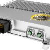

Bộ lập trình X90BC124.32-00
Thông số kỹ thuật bộ lập trình B&R X90BC124.32-00
đại lý X90BC124.32-00 | nhà phân phối X90BC124.32-00 | đại lý B&R | B&R Việt Nam
Bộ lập trình X90BC124.32-00 – B&R
Bộ lập trình X90BC124.32-00 do B&R sản xuất, sử dụng trong hệ thống điều khiển và tự động hoá công nghiệp. Thông số chính theo tài liệu kỹ thuật: bus controller CANopen; insulation voltage for gnd and housing 500 Veff; b&r id code 0xF23F; làm mát Fanless; chỉ số trạng thái No. ONTIDA cung cấp bộ lập trình X90BC124.32-00 kèm tài liệu kỹ thuật và tư vấn model thay thế khi mã cũ ngừng sản xuất.
Thông số kỹ thuật Bộ lập trình X90BC124.32-00
Mô tả ngắn gọn
| Bus controller | CANopen |
Thông tin chung
| Insulation voltage for GND and housing | 500 Veff |
| B&R ID code | 0xF23F |
| Làm mát | Fanless |
| Chỉ số trạng thái | No |
| Chẩn đoán | |
| Module run/error | Yes, using software |
| Bộ điều khiển B&R function | Yes, using software |
| Tiêu thụ điện năng |
With active 5 V sensor power supply: 3 to 3.3 W With active 10 V sensor power supply: 6.1 to 9 W |
| Chứng nhận | |
| UN ECE-R10 | Yes |
| CE | Yes |
| UKCA | Yes |
Input power supply
| Input voltage | 9 to 32 VDC |
| Input current | |
| V_CPU | Max. 3 A |
| V_I/O | Max. 10 A per pin |
| Integrated protection | |
| V_CPU | No, required fuse max. 3 A slow-blow |
| V_I/O | No, required fuse max. 10 A slow-blow |
Bộ điều khiển B&R
| Đồng hồ thời gian thực | No |
| FPU | Yes |
| Bộ xử lý | |
| Kiểu | ARM Cortex-M4 |
| Bộ xử lý I/O tích hợp | Processes I/O data points in the background |
| Option boards | 0 |
Giao diện
| CAN | |
| Khác nhau | Connection on CMC header X1 |
| Tỷ lệ chuyển nhượng | Max. 1 Mbit/s |
| Max. distance | 1000 m |
| Terminating resistor | External 120 Ω must be provided. |
Multi-function inputs
| Multifunction digital inputs (MF-DI) | |
| Quantity | 4 |
| Functions | Sink/Source circuit, configurable software input filter, fixed or ratiometrically configurable threshold value, open-circuit and short-circuit detection. Input frequency max. 50 kHz, period duration or gate measurement, AB/ABR encoder, DF/edge counter, rising or falling edge Measurement range 0 to 32 V, configurable analog filter, configurable limit values, integrated input protection |
| Multifunction analog inputs (MF-AI) | |
| Quantity | 12 |
| Functions | Measurement ranges 0 to 10 V / 0 to 32 V / 0 to 20 mA / 4 to 20 mA / 0 to 4 kΩ / -80 to 270°C, configurable analog filter, configurable limit values, integrated input protection Measurement ranges 0 to 10 V / 0 to 32 V / 0 to 20 mA / 4 to 20 mA, configurable analog filter, configurable limit values, integrated input protection Measurement ranges 0 to 10 V / 0 to 32 V, configurable analog filter, configurable limit values, integrated input protection Max. 20 mA Sink/Source circuit, configurable software input filter, fixed or ratiometrically configurable threshold value, open-circuit and short-circuit detection. |
Multi-function outputs
| Multifunction digital outputs (MF-DO) | |
| Quantity | 4 |
| Functions | 4 A nominal current, 2 channels source circuit, 2 channels sink circuit, integrated output protection, parallel connection of source channels possible. Sink circuit, configurable software input filter, fixed configurable threshold value, open-circuit and short-circuit detection. Measurement range 0 to 32 V, configurable analog filter, configurable limit values, integrated input protection |
| Multifunction PWM outputs (MF-PWM) | |
| Quantity | 8 |
| Functions | 4 A nominal current, source circuit, integrated output protection, parallel connection possible. 4 A nominal current, PWM frequency 15 Hz to 1 kHz, current control function, integrated output protection, parallel connection possible, configurable switch-on/switch-off ramp, dither Sink circuit, configurable software input filter, fixed or ratiometrically configurable threshold value, open-circuit and short-circuit detection. Measurement range 0 to 32 V, configurable analog filter, configurable limit values, integrated input protection |
| Multifunction PVG outputs (MF-PVG) | |
| Quantity | 4 |
| Functions | 10 mA nominal current at 24 V, sink/source circuit, integrated output protection. 10 mA nominal current at 24 V, PVG frequency 15 Hz to 1 kHz. Sink/Source circuit, configurable software input filter, fixed configurable threshold value, open-circuit and short-circuit detection. Measurement range 0 to 32 V, configurable analog filter, configurable limit values, integrated input protection |
Digital inputs
| Quantity | 0 to 32, depends on the use of multifunction inputs/outputs |
| Nominal voltage | 12 / 24 VDC |
| Input voltage | 9 to 32 VDC |
| Input current at 24 VDC |
MF-DI: 1.2 mA MF-AI: 1.2 mA MF-DO_plus: <1 mA MF-PWM: <1 mA MF-PVG: Typ. 10 mA |
| Input circuit | Sink/Source, configurable |
| Input filter | |
| Hardware |
MF-DI: 3 μs if switching threshold = 50% supply voltage MF-AI: 600 μs if switching threshold = 50% supply voltage MF-DO: 300 μs MF-PWM: 150 μs |
| Software | Default 1 ms, configurable between 0 and 25 ms in 0.1 ms increments |
| Input resistance | MF-AI and MF-DI: Typ. 22 kΩ |
| Additional functions | Counter functions (inputs 13 to 16) Edge detection: Max. 50 kHz Period duration / Gate measurement: Max. 3.5 kHz ABR, AB and DF counters |
| Input frequency | MF-DI: Max. 50 kHz |
| Switching threshold |
MF-DI: 50% of supply voltage MF-AI: Switching threshold and hysteresis configurable with software MF-DO: 50% supply voltage MF-PWM: 50% supply voltage |
Analog inputs
| Input | 0 to 10 V / 0 to 32 V / 0 to 20 mA / 4 to 20 mA / 0 to 4 kΩ / -80 to 270°C |
| Digital converter resolution | 12-bit |
| Conversion time | 250 μs |
| Output format | |
| Data type | INT, UINT (resistance) |
| Voltage |
Voltage 0 to 10 V: INT 0x0000 – 0x7FFF / 1 LSB = 0x0008 = 2.44 mV Voltage 0 to 32 V: INT 0x0000 – 0x7FFF / 1 LSB = 0x0008 = 7.81 mV |
| Current | INT 0x0000 – 0x7FFF / 1 LSB = 0x0008 = 4.9 μA |
| Resistance | 0 to 4000, 1 Ω increments |
| Nhiệt độ input | -80 to 270, 0.1°C increments |
| Input impedance in signal range | |
| Voltage | >100 kΩ |
| Current | – |
| Measurement current resistance / Nhiệt độ input | <1.2 mA |
| Load | |
| Voltage | – |
| Current | <300 Ω |
| Open-circuit detection | From the application |
| Reverse polarity protection | Yes |
| Conversion procedure | SAR |
| Input filter | Low-pass filter / Cutoff frequency voltage input / Current input 200 Hz |
| Max. error | |
| Voltage | |
| Gain | <1% |
| Offset | <1% |
| Current | |
| Gain | <1% |
| Offset | <1% |
| Resistance | <1% |
| Nhiệt độ input | <1% |
| Max. gain drift | |
| Voltage | <0.03%/°C |
| Current | <0.04%/°C |
| Resistance | 0.034% |
| Nhiệt độ input | 0.024% |
| Max. offset drift | |
| Voltage | <0.006%/°C |
| Current | <0.02%/°C |
| Resistance | 0.0018%/°C |
| Nhiệt độ input | 0.027%/°C |
Sensor power supply
| Voltage | 5 / 10 V |
| Current | Maximum 400 mA, accuracy: ±4% |
Digital outputs
| Quantity | 0 to 23, depends on the use of multifunction outputs |
| Khác nhau |
7x MF-AI, LED driver: Current-sinking 2x MF-DO_minus: Current-sinking 2x MF-DO_plus: Current-sourcing, channels can be connected in parallel (max. 6.5 A). 8x MF-PWM: Current-sourcing, channels can be connected in parallel. 4x MF-PVG: Current-sourcing/Current-sinking |
| Nominal voltage | 12 / 24 VDC |
| Digital converter resolution | 12-bit |
| Output format |
MF-AI LED driver: INT 0x0000 to 0x7FFF / 1 LSB = 0x0008 = 4.9 µA MF-DO_plus: INT 0x0000 to 0x7FFF / 1 LSB = 0x0008 = 1.22 mA MF-DO_minus: INT 0x0000 to 0x7FFF / 1 LSB = 0x0008 = 2.21 mA MF-PWM: INT 0x0000 to 0x7FFF / 1 LSB = 0x0008 = 1.22 mA MF-PVG: INT 0x0000 to 0x7FFF / 1 LSB = 0x0008 = 7.81 mV |
| Nominal output current |
MF-AI LED driver: 20 mA MF-DO: 4 A MF-PWM: 4 A MF-PVG: 10 mA |
| Output protection | Shutdown in the event of overcurrent or short circuit, integrated protection for switching inductive loads |
| Diagnostic status | Overload |
| Leakage current when the output is switched off |
MF-AI LED driver: 10 µA MF-DO: 10 μA MF-PWM: 10 μA MF-PVG: 10 µA |
| RDS(on) |
MF-AI LED driver: 2 Ω MF-DO_minus: 70 mΩ MF-DO_plus: 50 mΩ MF-PWM: 50 mΩ MF-PVG: 2 Ω |
| Residual voltage | <1 V at 4 A nominal current |
| Peak short-circuit current |
MF-AI LED driver: 20 mA MF-DO_minus: Max. 24 A MF-DO_plus: Max. 90 A MF-PWM: Max. 90 A MF-PVG: Max. 10 mA |
| Switching frequency | |
| Resistive load |
MF-AI LED driver: Max. 100 Hz MF-DO: Max. 100 Hz MF-PWM: 15 Hz to 1 kHz MF-PVG: 15 Hz to 1 kHz |
| Max. error at 25°C | |
| Gain |
MF-AI LED driver: <1% MF-DO: <12% MF-PWM: <0.2% MF-PVG: <5% |
| Offset |
MF-AI LED driver: <1% MF-DO: <1% MF-PWM: <0.1% MF-PVG: <1% |
| Max. gain drift |
MF-DO: <0.2%/°C MF-PWM: <0.04%/°C |
| Max. offset drift |
MF-DO: <0.005%/°C MF-PWM: <0.005%/°C |
| Braking voltage when switching off inductive loads | MF-DO: Typ. 64 VDC |
| Switching delay | MF-DO: Max. 2 ms |
| Output voltage | |
| Nominal | 9 to 32 VDC |
| Current measurement | |
| Current measurement range |
MF-AI LED driver: 0 to 20 mA MF-DO_plus: 0 to 20 A MF-DO_minus: 0 to 5 A MF-PWM: 0 to 5 A |
| Sampling frequency |
MF-AI LED driver: 250 µs MF-DO: 250 μs MF-PWM: 50 μs MF-PVG: 250 µs |
PWM output
| Quantity |
0 to 8x 4 A Depends on the use of multifunction outputs |
| Nominal voltage | 12 / 24 VDC |
| Supply voltage (permissible range) | 9 to 32 VDC |
| Digital converter resolution | 12-bit |
| Output format | MF-PWM: INT 0x0000 to 0x7FFF / 1 LSB = 0x0008 = 1.22 mA |
| PWM frequency | 15 Hz to 1 kHz |
| Duty cycle | 0 to 32767, equivalent 0 to 100% |
| Max. error at 25°C | |
| Gain | <0.2% |
| Offset | <0.1% |
| Max. gain drift | <0.04%/°C |
| Max. offset drift | <0.005%/°C |
| Common mode error | 0.015%/V |
| Output protection | Thermal shutdown in the event of overcurrent or short circuit, integrated protection for switching inductive loads |
| Khác nhau | Current-sourcing FET, channels can be connected in parallel in pairs. |
| Diagnostic status | Overload |
| Peak short-circuit current | 90 A |
| Current measurement | |
| Current measurement range | 0 to 5 A |
| Conversion time | 250 μs |
Tính chất điện
| Summation current | |
| Complete system | Max. 25.5 A |
Điều kiện hoạt động
| Hướng lắp đặt | |
| Any | Yes |
| Degree of protection | IP69K |
Điều kiện môi trường xung quanh
| Nhiệt độ | |
| Hoạt động | -40 to 85°C housing surface |
| Giảm tải | – |
| Lưu trữ | -40 to 85°C |
| Transport | -40 to 85°C |
| Độ ẩm tương đối | |
| Hoạt động | 5 to 100%, condensing |
| Lưu trữ | 5 to 95%, non-condensing |
| Transport | 5 to 95%, non-condensing |
Tính chất cơ học
| Dimensions | |
| Width | 153 mm |
| Length | 140 mm |
| Height | 44 mm |
| Weight | 700 g |
Sản phẩm liên quan
- Bộ lập trình X90CP154.60-00
- Bộ lập trình X20PS9602
- Bộ lập trình X90CP154.60-S1
- Bộ lập trình X20PS9600
- Bộ lập trình X20BB52
- Bộ lập trình X20CP1382
- Bộ lập trình X20EM1613
Xem thêm toàn bộ Bộ lập trình hoặc quay lại trang chủ ONTIDA.
Câu hỏi thường gặp về Bộ lập trình X90BC124.32-00
Bộ lập trình X90BC124.32-00 dùng để làm gì?
Bộ lập trình X90BC124.32-00 của B&R là bộ lập trình dùng trong tủ điện và hệ thống điều khiển tự động hoá công nghiệp, lắp đặt theo đúng tài liệu kỹ thuật của nhà sản xuất.
Thông số kỹ thuật chính của X90BC124.32-00 là gì?
Bus controller: CANopen; Insulation voltage for GND and housing: 500 Veff; B&R ID code: 0xF23F; Làm mát: Fanless; Chỉ số trạng thái: No. Bảng thông số đầy đủ được trình bày ngay trên trang này.
X90BC124.32-00 còn hàng không và thời gian giao bao lâu?
Tình trạng hàng của X90BC124.32-00 thay đổi theo từng thời điểm. Mã có sẵn giao trong 1–2 ngày làm việc, mã phải đặt theo lịch nhập khẩu cần nhiều thời gian hơn — vui lòng liên hệ để được xác nhận.
Giá X90BC124.32-00 được tính thế nào?
Giá X90BC124.32-00 phụ thuộc số lượng, thời gian giao và tình trạng tồn kho nên không niêm yết cố định. Vui lòng liên hệ để nhận báo giá theo nhu cầu thực tế.
Có model nào thay thế X90BC124.32-00 không?
Một số mã cùng nhóm có thể xem xét thay thế hoặc dùng kèm: Bộ lập trình X90CP154.60-00, Bộ lập trình X20PS9602, Bộ lập trình X90CP154.60-S1. Cần đối chiếu thông số kỹ thuật trước khi thay thế.
Brand
B&R
Sản phẩm tương tự

Bộ lập trình

Bộ lập trình

Bộ lập trình
Bộ lập trình

Bộ lập trình

Bộ lập trình

Bộ lập trình
Bộ lập trình