
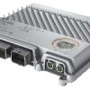

Bộ lập trình X90CP174.48-00
Thông số kỹ thuật bộ lập trình B&R X90CP174.48-00
đại lý X90CP174.48-00 | nhà phân phối X90CP174.48-00 | đại lý B&R | B&R Việt Nam
Bộ lập trình X90CP174.48-00 – B&R
Bộ lập trình X90CP174.48-00 do B&R sản xuất, sử dụng trong hệ thống điều khiển và tự động hoá công nghiệp. Thông số chính theo tài liệu kỹ thuật: mô-đun hệ thống Bộ điều khiển B&R; insulation voltage for gnd and housing 500 Veff; b&r id code 0xEB3F; làm mát Fanless; module run/error Yes, using LED status indicator and software. ONTIDA cung cấp bộ lập trình X90CP174.48-00 kèm tài liệu kỹ thuật và tư vấn model thay thế khi mã cũ ngừng sản xuất.
Thông số kỹ thuật Bộ lập trình X90CP174.48-00
Mô tả ngắn gọn
| Giao diện | 1x Ethernet, 1x USB, 3x CAN bus, 1x POWERLINK |
| Mô-đun hệ thống | Bộ điều khiển B&R |
Thông tin chung
| Insulation voltage for GND and housing | 500 Veff |
| B&R ID code | 0xEB3F |
| Làm mát | Fanless |
| Chỉ số trạng thái | Bộ điều khiển B&R function, overtemperature, Ethernet, POWERLINK |
| Chẩn đoán | |
| Module run/error | Yes, using LED status indicator and software |
| CPU function | Yes, using LED status indicator |
| Ethernet | Yes, using LED status indicator |
| Hỗ trợ | |
| Bộ điều khiển B&R redundancy | No |
| Hỗ trợ dữ liệu sức khỏe lưu trữ | Yes |
| ACOPOS support | Yes |
| reACTION-capable I/O channels | No |
| Hỗ trợ thành phần trực quan | Yes |
| Tiêu thụ điện năng without interface module and USB |
CPU at Ue = 9 / 32 V: 3.3 / 3.9 W I/O at Ue = 9 / 32 V: 0.9 / 3.4 W |
| Chứng nhận | |
| UN ECE-R10 | Yes |
| CE | Yes |
| UKCA | Yes |
Input power supply
| Input voltage | 9 to 32 VDC |
| Reset switching threshold | 6.8 V ±5% |
| Input current | |
| V_CPU | Max. 5 A |
| V_I/O | Max. 10 A per connection pin |
| Integrated protection | |
| V_CPU | No, required fuse 5 A slow-blow |
| V_I/O | No, required fuse 10 A slow-blow per connection pin |
| Overvoltage | 48 V ≤5 minutes |
| Overvoltage protection | Load dump pulse A 202 V Ri = 4 Ω |
| Reverse polarity protection | -48 V ≤5 minutes |
Bộ điều khiển B&R
| Đồng hồ thời gian thực | Resolution 1 s, retention min. 48 hours, typ. 250 hours at 25°C, precision ±30 ppm over the entire temperature range |
| FPU | Yes |
| Bộ xử lý | |
| Kiểu | ARM Cortex-A9 |
| Tần số đồng hồ | 650 MHz |
| L1 cache | |
| Mã dữ liệu | 32 kB |
| Mã chương trình | 32 kB |
| L2 cache | 512 kB |
| Bộ xử lý I/O tích hợp | Processes I/O data points in the background |
| Option boards | 4 |
| Các biến số | 32 kB FRAM, retention >10 years |
| Thời gian chu kỳ lớp nhiệm vụ ngắn nhất | 400 µs |
| Bộ nhớ chuẩn | |
| RAM | 256 MB DDR3 SDRAM |
| Bộ nhớ ứng dụng | |
| Kiểu | 1 GB flash memory |
| Lưu giữ dữ liệu | 10 years |
| Lượng dữ liệu có thể ghi | |
| Đảm bảo | 100 TB |
| Kết quả trong 5 năm | 54.8 GB/day |
| Đảm bảo erase/write cycles | 100,000 |
| Mã sửa lỗi (ECC) | Yes |
Giao diện
| Interface IF2 | |
| Kiểu | Ethernet |
| Khác nhau | M12, D-coded |
| Chiều dài dòng | Max. 100 m between 2 stations (segment length) |
| Tỷ lệ chuyển nhượng | 10/100 Mbit/s |
| Transfer | |
| Lớp vật lý | 10BASE-T / 100BASE-TX |
| Half-duplex | Yes |
| Full-duplex | Yes |
| Autonegotiation | Yes |
| Auto-MDI/MDIX | Yes |
| Interface IF3 | |
| Fieldbus | POWERLINK managing or controlled node |
| Kiểu | Kiểu 6 |
| Khác nhau | M12, D-coded |
| Chiều dài dòng | Max. 100 m between 2 stations (segment length) |
| Tỷ lệ chuyển nhượng | 100 Mbit/s |
| Transfer | |
| Lớp vật lý | 100BASE-TX |
| Half-duplex | Yes |
| Full-duplex | No |
| Autonegotiation | Yes |
| Auto-MDI/MDIX | Yes |
| Interface IF4 | |
| Kiểu | USB 1.1/2.0 |
| Khác nhau | Kiểu A (under service access window) |
| Max. output current | 500 mA |
| Interface IF7 | |
| Connection designation | CAN1 |
| Kiểu | CAN bus |
| Khác nhau | Connection on CMC header X1.A |
| Max. distance | 1000 m |
| Tỷ lệ chuyển nhượng | Max. 1 Mbit/s |
| Terminating resistor | External 120 Ω must be provided. |
| Interface IF8 | |
| Connection designation | CAN2 |
| Kiểu | CAN bus |
| Khác nhau | Connection on CMC header X1.A |
| Max. distance | 1000 m |
| Tỷ lệ chuyển nhượng | Max. 1 Mbit/s |
| Terminating resistor | External 120 Ω must be provided. |
| Interface IF9 | |
| Connection designation | CAN3 |
| Kiểu | CAN bus |
| Khác nhau | Connection on CMC header X1.A |
| Max. distance | 1000 m |
| Tỷ lệ chuyển nhượng | Max. 1 Mbit/s |
| Terminating resistor | External 120 Ω must be provided. |
Multi-function inputs
| Multifunction digital inputs (MF-DI) | |
| Quantity | 8 |
| Functions | Sink/Source circuit – Configurable per channel, configurable software input filter, counter function up to 50 kHz counter frequency (AB, ABR, DF, edge counter), edge detection with timestamp (for period duration, gate measurement, differential time measurement) |
| Multifunction analog inputs (MF-AI) | |
| Quantity | 16 |
| Functions | Sink/Source circuit – Configurable per channel, configurable software input filter, fixed or ratiometrically configurable switching threshold, open-circuit and short-circuit detection. Configurable software input filter, open-circuit and short-circuit detection. Measurement range 0 to 10 V / 0 to 32 V / 0 to 20 mA / 4 to 20 mA / 1 to 50 kΩ / temperature inputs (Pt1000 characteristic curve), configurable analog filter, configurable ramp limit, configurable threshold values, integrated input protection |
Multi-function outputs
| Multifunction digital outputs (MF-DO) | |
| Quantity | 8 |
| Functions | 4 A nominal current, source circuit, integrated output protection per channel, configurable overload monitoring per channel, central cutoff via relay, parallel connection, current measurement, error state with configurable error filter. Sink/Source circuit configurable per channel, configurable software input filter |
| Multifunction PWM outputs (MF-PWM) | |
| Quantity |
PWM 4 A: 11 PWM 6 A: 5 |
| Functions | 4 A nominal current (PWM 4 A), 6 A nominal current (PWM 6 A), sink/source circuit, integrated output protection per channel, configurable overload monitoring per channel, central cutoff via relay, parallel connection, current measurement, error state with configurable error filter. 4 A nominal current (PWM 4 A), 6 A nominal current (PWM 6 A), PWM frequency 15 Hz to 4 kHz, sink/source circuit, integrated output protection per channel, configurable overload monitoring per channel, central cutoff via relay, parallel connection, current measurement (asynchronous or synchronous to PWM period), configurable load current distribution of PWM outputs, dither. 4 A nominal current (PWM 4 A), 6 A nominal current (PWM 6 A), PWM frequency 15 Hz to 8 kHz (at load), integrated output protection per channel, configurable overload monitoring per channel, central cutoff via relay, parallel connection, current measurement (asynchronous or synchronous to PWM period), configurable load current distribution of PWM outputs, dither. Sink/Source circuit configurable per channel, configurable software input filter |
Digital inputs
| Quantity | 8 to 48, depends on the use of multifunction inputs/outputs |
| Nominal voltage | 12 / 24 VDC |
| Input voltage | 9 to 32 VDC |
| Input current at 24 VDC |
MF-DI: Typ. 1.2 / 2.5 / 3.6 mA, configurable MF-AI: Typ. 1.2 / 2.5 / 3.6 mA, configurable MF-DO: Typ. 2.5 mA MF-PWM: Typ. 2.5 mA |
| Input circuit | Sink/Source, configurable |
| Input filter | |
| Hardware |
MF-DI: 3 μs if switching threshold = 50% supply voltage MF-AI: 300 μs if switching threshold = 50% supply voltage MF-DO: 300 μs MF-PWM: 150 μs |
| Software | Default 1 ms, configurable between 0 and 25 ms in 0.1 ms increments |
| Input resistance |
MF-AI and MF-DI: Typ. 6.5 / 9 / 18 kΩ, configurable MF-DO and MF-PWM: 9 kΩ |
| Input frequency | MF-DI: Max. 50 kHz |
| Switching threshold |
MF-DI: 50% of supply voltage MF-AI: Switching threshold and hysteresis configurable with software MF-DO: 42% supply voltage MF-PWM: 42% supply voltage |
Analog inputs
| Input | 0 to 10 V / 0 to 32 V / 0 to 20 mA / 4 to 20 mA / 0 to 50 kΩ / Nhiệt độ inputs (Pt1000 characteristic curve) |
| Digital converter resolution | 12-bit |
| Conversion time | 160 μs |
| Output format | |
| Data type | INT, UINT (resistance) |
| Voltage |
Voltage 0 to 10 V: INT 0x0000 – 0x7FFF / 1 LSB = 0.305 mV Voltage 0 to 32 V: INT 0x0000 – 0x7FFF / 1 LSB = 0.97625 mV |
| Current | INT 0x0000 – 0x7FFF / 1 LSB = 0.610 µA |
| Resistance | 0 to 50000, 1 Ω increments |
| Nhiệt độ input | -2000 to 8500, 0.1°C increments |
| Input impedance in signal range | |
| Voltage | >100 kΩ |
| Current | – |
| Measurement current resistance / Nhiệt độ input | <1.6 mA |
| Load | |
| Voltage | – |
| Current | <300 Ω |
| Open-circuit detection | From the application |
| Conversion procedure | SAR |
| Input filter | First-order low-pass filter / cutoff frequency of voltage input 350 Hz, current input 200 Hz |
| Max. error | |
| Voltage | |
| Gain | <1% |
| Offset | <1% |
| Current | |
| Gain | <1% |
| Offset | <1% |
| Resistance | <1% |
| Nhiệt độ input | <1% |
| Max. gain drift | |
| Voltage | <0.03%/°C |
| Current | <0.04%/°C |
| Resistance | 0.034% |
| Nhiệt độ input | 0.024% |
| Max. offset drift | |
| Voltage | <0.006%/°C |
| Current | <0.02%/°C |
| Resistance | 0.0018%/°C |
| Nhiệt độ input | 0.027%/°C |
| Nonlinearity | <0.05%, <0.2% (resistance, temperature inputs) |
Sensor power supply
| Voltage |
Sensor power supply 1: 5/10 V Sensor power supply 2: 5 V |
| Current |
Sensor power supply 1: Max. 400 mA, accuracy: ±3% Sensor power supply 2: Max. 500 mA, accuracy: ±4% |
Digital outputs
| Quantity | 0 to 24, depends on the use of multifunction outputs |
| Khác nhau |
MF-DO_plus: Positive switching, 2 channels can be connected in parallel (max. 8 A). MF-PWM: Positive/Negative switching FET, channels can be connected in parallel. |
| Nominal voltage | 12 / 24 VDC |
| Switching voltage |
MF-DO, MF-PWM: V_IO -15% MF-PVG, MF-AI (ratiometric output) : V_CPU – 15% |
| Digital converter resolution | 12-bit |
| Output format |
INT MF-DO: INT 0x0000 to 0x7FFF / 1 LSB = 610 µA MF-PWM: INT 0x8001 to 0x7FFF / 1 LSB = 305 µA |
| Nominal output current |
MF-DO: 4 A MF-PWM: 4 A / 6 A |
| Output protection | Thermal shutdown in the event of overcurrent or short circuit, integrated protection for switching inductive loads |
| Diagnostic status | Overload |
| Leakage current when the output is switched off |
MF-DO: 10 μA MF-PWM: 20 μA |
| RDS(on) |
MF-DO: 80 mΩ MF-PWM: 50 mΩ |
| Residual voltage | <1 V at 4 A nominal current |
| Peak short-circuit current |
MF-DO: 90 A MF-PWM: 50 A |
| Switching frequency | |
| Resistive load | MF-DO: Max. 250 Hz |
| Inductive load | MF-DO: Load current 4 A: Max. 4 mH (see section “Switching inductive loads”) |
| Braking voltage when switching off inductive loads | MF-DO: Typ. 64 VDC |
| Switching delay | MF-DO: Max. 150 μs |
| Output voltage | |
| Nominal | 9 to 32 VDC |
| Sampling time |
MF-DO: 160 μs MF-PWM: 40 μs |
| Current measurement | |
| Current measurement range |
MF-DO: 0 to 20 A MF-PWM: ±10 A |
| Max. error at 25°C | |
| Gain |
MF-DO: <12% MF-PWM: <0.2% |
| Offset |
MF-DO: <1% MF-PWM: <0.1% |
| Max. gain drift |
MF-DO: <0.2%/°C MF-PWM: <0.04%/°C |
| Max. offset drift |
MF-DO: <0.005%/°C MF-PWM: <0.005%/°C |
PWM output
| Quantity |
0 to 11x 4 A and 0 to 5x 6 A Depends on the use of multifunction outputs |
| Nominal voltage | 12 / 24 VDC |
| Supply voltage (permissible range) | 9 to 32 VDC |
| Digital converter resolution | 12-bit |
| Output format |
INT MF-PWM: INT 0x8001 to 0x7FFF / 1 LSB = 305 µA |
| PWM frequency | 15 Hz to 4 kHz |
| Duty cycle | 0 to 100%, resolution 0.16 µs |
| Max. error at 25°C | |
| Gain | MF-PWM: <0.2% |
| Offset | MF-PWM: <0.1% |
| Max. gain drift | MF-PWM: <0.04%/°C |
| Max. offset drift | MF-PWM: <0.005%/°C |
| Common mode error | MF-PWM: 0.015%/V |
| Output protection | Thermal shutdown in the event of overcurrent or short circuit, integrated protection for switching inductive loads |
| Khác nhau | Positive/Negative switching FET, channels can be connected in parallel. |
| Diagnostic status | Overload |
| Peak short-circuit current | 50 A (max. 0.2 ms) |
| Current measurement | |
| Current measurement range | MF-PWM: ±10 A |
| Conversion time | MF-PWM: 40 μs |
Tính chất điện
| Summation current | |
| Multifunction digital outputs (MF-DO) | Max. 20 A |
| Mainboard | Max. 40 A |
| Option boards | Max. 32 A |
| Complete system | Max. 70 A |
| Inrush current | Up to 500 A for <300 μs |
| Cách ly điện | Ethernet (IF2) and POWERLINK (IF3) isolated from each other and from other interfaces |
Điều kiện hoạt động
| Hướng lắp đặt | |
| Any | Yes |
| Độ cao lắp đặt so với mực nước biển | |
| 0 to 2000 m | Không có giới hạn |
| Mức độ bảo vệ mỗi EN 60529 | IP69K |
Điều kiện môi trường xung quanh
| Nhiệt độ | |
| Hoạt động | |
| Nằm ngang mounting orientation | -40 to 85°C housing surface |
| Thẳng đứng mounting orientation | -40 to 85°C housing surface |
| Giảm tải | See section “Giảm tải”. |
| Lưu trữ | -40 to 85°C |
| Transport | -40 to 85°C |
| Độ ẩm tương đối | |
| Hoạt động | 5 to 100%, condensing |
| Lưu trữ | 5 to 95%, non-condensing |
| Transport | 5 to 95%, non-condensing |
Tính chất cơ học
| Dimensions | |
| Width | 250 mm |
| Length | 231 mm |
| Height | 44 mm |
| Weight | Max. 2.3 kg |
Brief overview
| Content of delivery | 2x protective covers for unused female M12 connectors |
Sản phẩm liên quan
- Bộ lập trình X90CP174.48-S1
- Bộ lập trình X90CP174.24-00
- Bộ lập trình X90CP172.24-00
- Bộ lập trình X90CP154.60-S1
- Bộ lập trình X20BB67
- Bộ lập trình X20CP3684
- Bộ lập trình X20cBB57
Xem thêm toàn bộ Bộ lập trình hoặc quay lại trang chủ ONTIDA.
Câu hỏi thường gặp về Bộ lập trình X90CP174.48-00
Bộ lập trình X90CP174.48-00 dùng để làm gì?
Bộ lập trình X90CP174.48-00 của B&R là bộ lập trình dùng trong tủ điện và hệ thống điều khiển tự động hoá công nghiệp, lắp đặt theo đúng tài liệu kỹ thuật của nhà sản xuất.
Thông số kỹ thuật chính của X90CP174.48-00 là gì?
Mô-đun hệ thống: Bộ điều khiển B&R; Insulation voltage for GND and housing: 500 Veff; B&R ID code: 0xEB3F; Làm mát: Fanless; Module run/error: Yes, using LED status indicator and software. Bảng thông số đầy đủ được trình bày ngay trên trang này.
X90CP174.48-00 còn hàng không và thời gian giao bao lâu?
Tình trạng hàng của X90CP174.48-00 thay đổi theo từng thời điểm. Mã có sẵn giao trong 1–2 ngày làm việc, mã phải đặt theo lịch nhập khẩu cần nhiều thời gian hơn — vui lòng liên hệ để được xác nhận.
Giá X90CP174.48-00 được tính thế nào?
Giá X90CP174.48-00 phụ thuộc số lượng, thời gian giao và tình trạng tồn kho nên không niêm yết cố định. Vui lòng liên hệ để nhận báo giá theo nhu cầu thực tế.
Có model nào thay thế X90CP174.48-00 không?
Một số mã cùng nhóm có thể xem xét thay thế hoặc dùng kèm: Bộ lập trình X90CP174.48-S1, Bộ lập trình X90CP174.24-00, Bộ lập trình X90CP172.24-00. Cần đối chiếu thông số kỹ thuật trước khi thay thế.
Brand
B&R
Sản phẩm tương tự

Bộ lập trình
Bộ lập trình

Bộ lập trình

Bộ lập trình

Bộ lập trình

Bộ lập trình
Bộ lập trình

Bộ lập trình